|
 |
 |
|
|
Characteristics
Vertical System Analog Channels
|
Characteristic |
MSO3012
DPO3012 |
MSO3014
DPO3014 |
MSO3032
DPO3032 |
MSO3034
DPO3034 |
MSO3054
DPO3054 |
|
Input Channels |
2 |
4 |
2 |
4 |
4 |
|
Analog Bandwidth (-3 dB) |
100 MHz |
100 MHz |
300 MHz |
300 MHz |
500 MHz |
|
Calculated Rise Time
5 mV/div (typical) |
3.5 ns |
3.5 ns |
1.17 ns |
1.17 ns |
700 ps |
|
Hardware Bandwidth Limits |
20 MHz |
20 MHz, 150 MHz |
|
Input Coupling |
AC, DC, GND |
|
Input Impedance |
1 MΩ ±1%, 75 Ω ±1%, 50 Ω ±1% |
|
Input Sensitivity Range, 1 MΩ |
1 mV/div to 10 V/div |
|
Input Sensitivity Range, 75 Ω, 50 Ω |
1 mV/div to 1 V/div |
|
Vertical Resolution |
8 bits (11 bits with Hi Res) |
|
Maximum Input Voltage, 1 MΩ |
300 VRMS with peaks ≤ ±450 V |
|
Maximum Input Voltage, 75 Ω, 50 Ω |
5 VRMS with peaks ≤ ±20 V |
|
DC Gain Accuracy |
±1.5% for 5 mV/div and above
±2.0% for 2 mV/div
±2.5% for 1 mV/div |
|
Channel-to-Channel Isolation
(Any Two Channels at Equal Vertical Scale) |
≥100:1 at ≤100 MHz and ≥30:1 at >100 MHz up to the rated BW |
Offset Range
|
Range |
1 MΩ |
50 Ω, 75 Ω |
|
1 mV/div to 99.5 mV/div |
±1 V |
±1 V |
|
100 mV/div to 995 mV/div |
±10 V |
±5 V |
|
1 V/div |
±100 V |
±5 V |
|
1.01 V/div to 10 V/div |
±100 V |
NA |
Vertical System Digital Channels
|
Characteristic |
All MSO3000 Models |
|
Input Channels |
16 Digital (D15 to D0) |
|
Thresholds |
Threshold per set of 8 channels |
|
Threshold Selections |
TTL, CMOS, ECL, PECL, User Defined |
|
User-defined Threshold Range |
-15 V to +25 V |
|
Maximum Input Voltage |
-20 V to +30 V |
|
Threshold Accuracy |
±(100 mV +3% of threshold setting) |
|
Maximum Input Dynamic Range |
50 Vpk-pk (threshold setting dependent) |
|
Minimum Voltage Swing |
500 mVpk-pk |
|
Input Impedance |
101 kΩ |
|
Probe Loading |
8 pF |
|
Vertical Resolution |
1 bit |
Horizontal System Analog Channels
|
Characteristic |
All MSO3000 Models
All DPO3000 Models |
|
Maximum Sample Rate (all channels) |
2.5 GS/s |
|
Maximum Record Length
(all channels) |
5 Mpoints |
|
Maximum Duration of Time Captured at Highest Sample Rate
(all channels) |
2 ms |
|
Time-base Range (s/div) |
1 ns to 1000 s |
|
Time-base Delay Time Range |
-10 divisions to 5000 s |
|
Channel-to-Channel Deskew Range |
±100 ns |
|
Time-base Accuracy |
±10 ppm over any ≥1 ms interval |
Horizontal System Digital Channels
|
Characteristic |
All MSO3000 Models |
|
Maximum Sample Rate (Main, all channels) |
500 MS/s (2 ns resolution) |
|
Maximum Record Length (Main, all channels) |
5 Mpoints |
|
Maximum Sample Rate (MagniVu, all channels) |
8.25 GS/s (121.2 ps resolution) |
|
Maximum Record Length (MagniVu, all channels) |
10 kpoints centered on the trigger |
|
Minimum Detectable Pulse Width |
2.0 ns |
|
Channel-to-Channel Skew |
500 ps typical |
Trigger System
|
Characteristic |
Description |
|
Main Trigger Modes |
Auto, Normal, and Single |
|
Trigger Coupling |
DC, AC, HF reject (attenuates >50 kHz), LF reject (attenuates <50 kHz), noise reject (reduces sensitivity) |
|
Trigger Holdoff Range |
20 ns to 8 s |
Trigger Sensitivity
|
Characteristic |
Description |
|
Internal DC Coupled |
0.5 div from DC to 50 MHz, increasing to 1 div at rated bandwidth |
|
External
(Auxiliary Input) |
200 mV from DC to 50 MHz increasing to 500 mV at 250 MHz |
Trigger Level Range
|
Characteristic |
Description |
|
Any Channel |
±8 divisions from center of screen |
|
External
(Auxiliary Input) |
±8 V |
Trigger Modes
|
Mode |
Description |
|
Edge |
Positive or negative slope on any channel or front-panel auxiliary input. Coupling includes DC, AC, HF reject, LF reject, and noise reject. |
|
Sequence (B-trigger) |
Trigger Delay by Time - 8 ns to 8 s. Or Trigger Delay by Events - 1 to 9,999,999 events. |
|
Pulse Width |
Trigger on width of positive or negative pulses that are >, <, =, or ≠ a specified period of time. |
|
Runt |
Trigger on a pulse that crosses one threshold but fails to cross a second threshold before crossing the first again. |
|
Logic |
Trigger when any logical pattern of channels goes false or stays true for specified period of time. Any input can be used as a clock to look for the pattern on a clock edge. Pattern (AND, OR, NAND, NOR) specified for all analog and digital input channels defined as High, Low, or Dont Care. |
|
Setup and Hold |
Trigger on violations of both setup time and hold time between clock and data present on any of the input channels. |
|
Rise/Fall Time |
Trigger on pulse edge rates that are faster or slower than specified. Slope may be positive, negative, or either. |
|
Video |
Trigger on all lines, odd, even, or all fields on NTSC, PAL, and SECAM video signals. |
|
Extended Video (optional) |
Trigger on 480p/60, 576p/50, 720p/30, 720p/50, 720p/60, 875i/60, 1080i/50, 1080i/60, 1080p/24, 1080p/24sF, 1080p/25, 1080p/30, 1080p/50, 1080p/60, and custom bi-level and tri-level sync video standards. |
|
I2C (optional) |
Trigger on Start, Repeated Start, Stop, Missing ACK, Address (7 or 10 bit), Data, or Address and Data on I2C buses up to 10 Mb/s. |
|
SPI (optional) |
Trigger on SS, MOSI, MISO, or MOSI and MISO on SPI buses up to 10.0 Mb/s. |
|
CAN (optional) |
Trigger on Start of Frame, Frame Type (data, remote, error, overload), Identifier (standard or extended), Data, Identifier and Data, End of Frame, Missing ACK, or Bit Stuffing Error on CAN signals up to 1 Mb/s. Data can be further specified to trigger on ≤, <, =, >, ≥, or ≠ a specific data value. User-adjustable sample point is set to 50% by default. |
|
I2S/LJ/RJ/TDM (optional) |
Trigger on Word Select, Frame Sync, or Data. Data can be further specified to trigger on ≤, <, =, >, ≥, ≠ a specific data value, or inside or outside of a range.
Maximum data rate for I2S/LJ/RJ is 12.5 Mb/s.
Maximum data rate for TDM is 25 Mb/s. |
|
RS-232/422/485/UART (optional) |
Trigger on Tx Start Bit, Rx Start Bit, Tx End of Packet, Rx End of Packet, Tx Data, Rx Data, Tx Parity Error, and Rx Parity Error up to 10 Mb/s. |
|
LIN (optional) |
Trigger on Sync, Identifier, Data, Identifier and Data, Wakeup Frame, Sleep Frame, Errors such as Sync, Parity, or Checksum Errors up to 1 Mb/s (by LIN definition, 20 kb/s). |
|
Parallel (available on MSO models only) |
Trigger on a parallel bus data value. Parallel bus can be from 1 to 16 bits in size. Binary and Hex radices are supported. |
Acquisition Modes
|
Mode |
Description |
|
Sample |
Acquire sampled values. |
|
Peak Detect |
Captures glitches as narrow as 2 ns at all sweep speeds. |
|
Averaging |
From 2 to 512 waveforms included in average. |
|
Envelope |
Min-max envelope reflecting Peak Detect data over multiple acquisitions. |
|
Hi Res |
Real-time boxcar averaging reduces random noise and increases vertical resolution. |
|
Roll |
Scrolls waveforms right to left across the screen at sweep speeds slower than or equal to 40 ms/div. |
Waveform Measurements
|
Measurement |
Description |
|
Cursors |
Waveform and Screen. |
|
Automatic Measurements |
29, of which up to four can be displayed on screen at any one time. Measurements include: Period, Frequency, Delay, Rise Time, Fall Time, Positive Duty Cycle, Negative Duty Cycle, Positive Pulse Width, Negative Pulse Width, Burst Width, Phase, Positive Overshoot, Negative Overshoot, Peak to Peak, Amplitude, High, Low, Max, Min, Mean, Cycle Mean, RMS, Cycle RMS, Positive Pulse Count, Negative Pulse Count, Rising Edge Count, Falling Edge Count, Area and Cycle Area. |
|
Measurement Statistics |
Mean, Min, Max, Standard Deviation. |
|
Reference Levels |
User-definable reference levels for automatic measurements can be specified in either percent or units. |
|
Gating |
Isolate the specific occurrence within an acquisition to take measurements on, using either the screen, or waveform cursors. |
Power Measurements (Optional)
|
Measurement |
Description |
|
Power Quality Measurements |
VRMS, VCrest Factor, Frequency, IRMS, ICrest Factor, True Power, Apparent Power, Reactive Power, Power Factor, Phase Angle. |
|
Switching Loss Measurements |
Power Loss: Ton, Toff, Conduction, Total. |
|
Energy Loss: Ton, Toff, Conduction, Total. |
|
Harmonics |
THD-F, THD-R, RMS measurements. |
|
Graphical and table displays of harmonics. |
|
Test to IEC61000-3-2 Class A and MIL-STD-1399. |
|
Ripple Measurements |
Vripple and Iripple. |
|
Modulation Analysis |
Graphical display of +Pulse Width, -Pulse Width, Period, Frequency, +Duty Cycle, and -Duty Cycle modulation types. |
|
Safe Operating Area |
Graphical display and mask testing of switching device safe operating area measurements. |
|
dV/dt and dI/dt Measurements |
Cursor measurements of slew rate. |
Waveform Math
|
Characteristic |
Description |
|
Arithmetic |
Add, subtract, multiply, and divide waveforms. |
|
Math Functions |
Integrate, Differentiate, FFT. |
|
FFT |
Spectral magnitude. Set FFT Vertical Scale to Linear RMS or dBV RMS, and FFT Window to Rectangular, Hamming, Hanning, or Blackman-Harris. |
|
Advanced Math |
Define extensive algebraic expressions including waveforms, reference waveforms, math functions (FFT, Intg, Diff, Log, Exp, Sqrt, Sine, Cosine, Tangent), scalars, up to two user-adjustable variables and results of parametric measurements (Period, Freq, Delay, Rise, Fall, PosWidth, NegWidth, BurstWidth, Phase, PosDutyCycle, NegDutyCycle, PosOverShoot, NegOverShoot, PeakPeak, Amplitude, RMS, CycleRMS, High, Low, Max, Min, Mean, CycleMean, Area, CycleArea, and trend plots), e.g.,(Intg(Ch1 - Mean(Ch1)) × 1.414 × VAR1). |
Software
|
Product |
Description |
|
NI LabVIEW SignalExpress Tektronix Edition |
A fully interactive measurement software environment optimized for the MSO/DPO3000 Series, enables you to instantly acquire, generate, analyze, compare, import, and save measurement data and signals using an intuitive drag-and-drop user interface that does not require any programming.
Standard MSO/DPO3000 Series support for acquiring, controlling, viewing, and exporting your live signal data is permanently available through the software. The full version (SIGEXPTE) adds additional signal processing, advanced analysis, mixed signal, sweeping, limit testing, and user-defined step capabilities and is available for a 30-day trial period standard with each instrument. |
|
OpenChoice® Desktop |
Enables fast and easy communication between a Windows PC and the MSO/DPO3000 Series. Transfer and save settings, waveforms, measurements, and screen images. Included Word and Excel toolbars automate the transfer of acquisition data and screen images from the oscilloscope into Word and Excel for quick reporting or further analysis. |
|
IVI Driver |
Provides a standard instrument programming interface for common applications such as LabVIEW, LabWindows/CVI, Microsoft .NET, and MATLAB. |
|
eScope |
Enables control of the MSO/DPO3000 Series over a network connection through a standard web browser. Simply enter the IP address or network name of the oscilloscope and a web page will be served to the browser. |
Display Characteristics
|
Characteristic |
Description |
|
Display Type |
9 in. (228.6 mm) wide format liquid crystal TFT color display. |
|
Display Resolution |
800 horizontal × 480 vertical pixels (WVGA). |
|
Waveform Styles |
Vectors, Dots, Variable Persistence, Infinite Persistence. |
|
Graticules |
Full, Grid, Cross Hair, Frame, IRE and mV. |
|
Format |
YT and XY. |
|
Maximum Waveform Capture Rate |
>50,000 wfm/s. |
Input/Output Ports
|
Port |
Description |
|
USB 2.0 High-speed Host Port |
Supports USB mass storage devices, printers, and keyboards. One port available on rear panel and one on front panel. |
|
USB 2.0 High-speed Device Port |
Rear-panel connector allows for communication/control of oscilloscope through USBTMC or GPIB with a TEK-USB-488, and direct printing to all PictBridge-compatible printers. |
|
LAN Port |
RJ-45 connector, supports 10/100Base-T. |
|
Video Out Port |
DB-15 female connector, connect to show the oscilloscope display on an external monitor or projector. |
|
Auxiliary Input |
Front-panel BNC connector. Input Impedance 1 MΩ. Max input 300 VRMS CAT II with peaks ≤ ±450 V. |
|
Probe Compensator Output |
Front-panel pins
Amplitude: 2.5 V
Frequency: 1 kHz |
|
Trigger Out |
Rear-panel BNC connector, provides a negative-polarity pulse when the oscilloscope triggers. |
|
Kensington Style Lock |
Rear-panel security slot connects to standard Kensington-style lock. |
Power Source
|
Characteristic |
Description |
|
Power Source Voltage |
85 to 265 V ±10% |
|
Power Source Frequency |
45 to 440 Hz (85 to 265 V) |
|
Power Consumption |
120 W maximum |
|
Optional TekVPI® External Power Supply*1 |
Output Voltage: 12 V
Output Current: 5 A
Power Consumption: 50 W |
*1 Required when total oscilloscope probe power usage exceeds 20 W.
Physical Characteristics
|
Dimensions |
mm |
in. |
|
Height |
203.2 |
8 |
|
Width |
416.6 |
16.4 |
|
Depth |
147.3 |
5.8 |
|
Weight |
kg |
lb. |
|
Net |
4.17 |
9.2 |
|
Shipping |
8.62 |
19 |
|
Rackmount Configuration |
5U |
|
Cooling Clearance |
2 in. (51 mm) required on left side and rear of instrument |
Environmental
|
Characteristic |
Description |
|
Temperature |
|
Operating |
0 ºC to +50 ºC |
|
Nonoperating |
-40 ºC to +71 ºC |
|
Humidity |
|
Operating |
High: 30 ºC to 50 ºC, 5% to 45% Relative Humidity
Low: 0 ºC to 30 ºC, 5% to 95% Relative Humidity |
|
Nonoperating |
High: 30 ºC to 50 ºC, 5% to 45% Relative Humidity
Low: 0 ºC to 30 ºC, 5% to 95% Relative Humidity |
|
Altitude |
|
Operating |
3,000 meters (9,843 feet) |
|
Nonoperating |
12,000 meters (39,370 feet) |
|
Random Vibration |
|
Operating |
0.31 GRMS from 5 to 500 Hz, 10 minutes each axis, 3 axes, 30 minutes total |
|
Nonoperating |
2.46 GRMS from 5 to 500 Hz, 10 minutes each axis, 3 axes, 30 minutes total |
|
Regulatory |
|
Electromagnetic Compatibility |
EC Council Directive 2004/108/EC |
|
Safety |
UL61010-1:2004; CAN/CSA C22.2 No. 61010.1-04;
EN61010-1:2001; IEC61010-1:2001 |
Ordering Information
DPO3000 Models
|
Product |
Description |
|
DPO3012 |
100 MHz, 2.5 GS/s, 5M record length,
2-channel digital phosphor oscilloscope |
|
DPO3014 |
100 MHz, 2.5 GS/s, 5M record length,
4-channel digital phosphor oscilloscope |
|
DPO3032 |
300 MHz, 2.5 GS/s, 5M record length,
2-channel digital phosphor oscilloscope |
|
DPO3034 |
300 MHz, 2.5 GS/s, 5M record length,
4-channel digital phosphor oscilloscope |
|
DPO3054 |
500 MHz, 2.5 GS/s, 5M record length,
4-channel digital phosphor oscilloscope |
MSO3000 Models
|
Product |
Description |
|
MSO3012 |
100 MHz, 2.5 GS/s, 5M record length,
2+16 channel mixed-signal oscilloscope |
|
MSO3014 |
100 MHz, 2.5 GS/s, 5M record length,
4+16 channel mixed-signal oscilloscope |
|
MSO3032 |
300 MHz, 2.5 GS/s, 5M record length,
2+16 channel mixed-signal oscilloscope |
|
MSO3034 |
300 MHz, 2.5 GS/s, 5M record length,
4+16 channel mixed-signal oscilloscope |
|
MSO3054 |
500 MHz, 2.5 GS/s, 5M record length,
4+16 channel mixed-signal oscilloscope |
All Models Include: One P6139A 500 MHz, 10x Passive Probe per Analog Channel, Front Cover (200-5052-xx), User Manual, Documentation CD (063-4104-xx), OpenChoice® Desktop Software, NI LabVIEW SignalExpress Tektronix Edition LE Software, Calibration Certificate Documenting Traceability to National Metrology Institute(s) and ISO9001 Quality System Registration, Power Cord, Accessory Pouch (016-2008-xx), Three-year Warranty. Please specify power plug and manual language version when ordering.
MSO Models also Include: One P6316 16-channel logic probe and accessory kit.
Application Modules
|
Modules |
Description |
|
DPO3AUDIO |
Audio Serial Triggering and Analysis Module. Enables triggering on packet-level information on I2S, Left Justified, Right Justified, TDM, and custom audio buses, as well as analytical tools such as digital views of the signal, bus views, packet decoding, search tools, and packet decode tables with time stamp information. |
|
DPO3AUTO |
Automotive Serial Triggering and Analysis Module. Enables triggering on packet-level information on CAN bus and LIN bus as well as analytical tools such as digital views of the signal, bus views, packet decoding, search tools, and packet decode tables with time stamp information. |
|
DPO3COMP |
Computer Serial Triggering and Analysis Module. Enables triggering on packet-level information on RS-232/422/485/UART buses as well as analytical tools such as digital views of the signal, bus views, packet decoding, search tools, and packet decode tables with time stamp information. |
|
DPO3EMBD |
Embedded Serial Triggering and Analysis Module. Enables triggering on packet-level information on I2C and SPI buses as well as analytical tools such as digital views of the signal, bus views, packet decoding, search tools, and packet decode tables with time stamp information. Only two-wire SPI support available on DPO3012, DPO3032 models. |
|
DPO3PWR |
Power Analysis Module. Enables quick and accurate analysis of power quality, switching loss, harmonics, safe operating area (SOA), modulation, ripple, and slew rate (dI/dt, dV/dt). |
|
DPO3VID |
HDTV and Custom (nonstandard) Video Triggering Module. |
Instrument Options
Power Plug Options
|
Option |
Description |
|
Opt. A0 |
North America |
|
Opt. A1 |
Universal Euro |
|
Opt. A2 |
United Kingdom |
|
Opt. A3 |
Australia |
|
Opt. A5 |
Switzerland |
|
Opt. A6 |
Japan |
|
Opt. A10 |
China |
|
Opt. A11 |
India |
|
Opt. A99 |
No power cord |
Language Options*2
|
Option |
Description |
|
Opt. L0 |
English manual |
|
Opt. L1 |
French manual |
|
Opt. L2 |
Italian manual |
|
Opt. L3 |
German manual |
|
Opt. L4 |
Spanish manual |
|
Opt. L5 |
Japanese manual |
|
Opt. L6 |
Portuguese manual |
|
Opt. L7 |
Simplified Chinese manual |
|
Opt. L8 |
Traditional Chinese manual |
|
Opt. L9 |
Korean manual |
|
Opt. L10 |
Russian manual |
|
Opt. L99 |
No manual |
*2 Language options include translated front-panel overlay for the selected language(s).
Service Options*3
|
Option |
Description |
|
Opt. C3 |
Calibration Service 3 years. |
|
Opt. C5 |
Calibration Service 5 years. |
|
Opt. CA1 |
Provides a single calibration event, or coverage for the designated calibration interval, whichever comes first. |
|
Opt. D1 |
Calibration Data Report. |
|
Opt. D3 |
Calibration Data Report 3 years (with Opt. C3). |
|
Opt. D5 |
Calibration Data Report 5 years (with Opt. C5). |
|
Opt. R5 |
Repair Service 5 years (including warranty). |
*3 Probes and accessories are not covered by the oscilloscope warranty and Service Offerings. Refer to the datasheet of each probe and accessory model for its unique warranty and calibration terms.
Recommended Probes
|
Probe |
Description |
|
TAP1500 |
1.5 GHz TekVPI® active voltage probe. |
|
TAP1500X2 |
Bundle of Two 1.5 GHz Active Probes, single ended with TekVPI Interface. |
|
TDP0500 |
500 MHz TekVPI differential voltage probe with ±42 V differential input voltage. |
|
TDP1000 |
1 GHz TekVPI differential voltage probe with ±42 V differential input voltage. |
|
TCP0030 |
120 MHz TekVPI 30 Ampere AC/DC current probe. |
|
TCP0150 |
20 MHz TekVPI 150 Ampere AC/DC current probe. |
|
TCPA300/400*4 |
Current measurement systems amplifier. |
|
P5200 |
1.3 kV, 25 MHz high-voltage differential probe. |
|
P5205*4 |
1.3 kV, 100 MHz high-voltage differential probe. |
|
P5210*4 |
5.6 kV, 50 MHz high-voltage differential probe. |
|
P5100 |
2.5 kV, 100X high-voltage passive probe. |
|
ADA400A*4 |
100X, 10X, 1X, 0.1X high-gain differential amplifier. |
|
NEX-HD2HEADER |
Mictor connector breakout to 0.1 in. header pins. |
|
DPO3PWRBND Power Solution Bundle |
Includes P5205 and TDP0500 differential voltage probes, TCP0030 current probe, TPA-BNC adapter, deskew pulse generator (TEK-DPG), deskew fixture, and power analysis module (DPO3PWR) in a hard-sided carrying case. Bundle discount reflected in price. |
*4 Requires TekVPI® to TekProbe BNC adapter (TPA-BNC).
Recommended Accessories
|
Accessory |
Description |
|
071-2667-xx |
Service Manual (English only) |
|
TPA-BNC |
TekVPI to TekProbe BNC adapter |
|
TEK-DPG |
TekVPI deskew pulse generator signal source |
|
067-1686-xx |
Power Measurement Deskew and Calibration Fixture |
|
119-7465-xx*5 |
TekVPI® External Power Supply |
|
SIGEXPTE |
NI LabVIEW SignalExpress Tektronix Edition Software Full Version |
|
FPGAView-xx |
MSO Support for Altera and Xilinx FPGAs |
|
TEK-USB-488 |
GPIB-to-USB adapter |
|
ACD4000 |
Soft Transit Case |
|
HCTEK4321 |
Hard Transit Case (requires ACD4000) |
|
RMD3000 |
Rackmount Kit | | |
|
|
|
 |
|
 |
|
|
|
 |
|
 |
|
Descripcion
Osciloscopios de Señal Mixta de Fosforo Digital
MSO3014
Caracteristicas y Beneficios
Especificaciones Clave
Decodificacion y Disparo de Buses Seriales
- Opciones para Disparo Serial, y opciones de Decodificacion y Analisis Seriales I2C, SPI, CAN, LIN, RS232/422/485/UART
Analisis de Señales Mixtas Analogos y Digitales en una misma pantalla (Serie MSO)
- Disparo y busqueda automatizada en buses paralelos
- Disparo Setup and Hold en multiples canales
- Adquisicion MagniVu de alta velocidad provee 121.2 ps de resolucion en tiempo en los canales digitales
Facil de Usar
- Controles Patentados Wave Inspector® Proveen eficiencia sin precedentes en el Analiss de Formas de Onda
- Pantalla de 9 Pulgadas (229 mm) WVGA Widescreen de Color
- USB 2.0 en el Panel frontal para almacenamiento facil y rapido
- Puerto de dispositivo USB 2.0 para control del osciloscopio usando conexion directa a la PCusando USBTMC
-
Puerto Ethernet
-
Conectividad Plug n Play Para Soluciones de Software de Analisis
- Control Remoto e*Scope para Visualizacion de Resultados y Control
-
Interface TekVPI® que soporta puntas Activas, Diferenciales y de Corriente para Ajuste de escala y unidades de medicion de manera automatica
-
Pequeño y Ligero solo 5.4 pulgadas (137mm) de profundo y 9 lbs. (4 kg) de peso.
Aplicaciones
- Diseño y Depuracion de Electronica Embebida
- Investigacion en Fenomenos de Transientes
- Mediciones de Potencia
- Diseño y Servicio de Video
- Analisis Espectral
- Diseño y Depuracion de Electronica Automotriz
- Prueba en Manofactura y Control de Calidad
- Diseño y Analisis Electro-mecanico
- Desarrollo de productos Bio-medicos
- Control Industrial
Osciloscopios de Fósforo Digital de la
Serie DPO3000
El poder de resolver problemas rápidamente
La Serie de Osciloscopios de Fósforo Digital DPO3000, le proporcionan
el desempeño que usted necesita para visualizar aún las señales más demandantes.
Está familia cuenta con modelos en el rango de 100 MHz a 500 MHz de
ancho de banda y en todos los modelos se ofrece un mínimo de sobremuestreo
de 5X y una interpolación de sen (x)/x de forma estándar, usted puede
tener la confianza de que aún los transitorios más rápidos serán capturados
y desplegados de manera exacta. La longitud de registro estándar de 5M
en todos los canales le permite capturar largas ventanas de actividad de
la señal, manteniendo la resolución de tiempo. La velocidad de captura de
50,000 formas de onda por segundo, aumenta la probabilidad de captura de
señales elusivas (glitches) y de otros eventos muy poco frecuentes.
La Serie DPO3000 le ofrece una variedad de soluciones analíticas incluyendo
cursores, 29 mediciones automáticas, estadísticas y operaciones matemáticas.
A pesar de su tamaño reducido (sólo 5.4 pulg de profundidad) y de su peso
ligero (9 lb.), la serie DPO3000 le ofrece un desempeño excepcional, una
gran pantalla ancha a color de 9 pulg. (WVGA) y una perilla de control vertical
por canal.
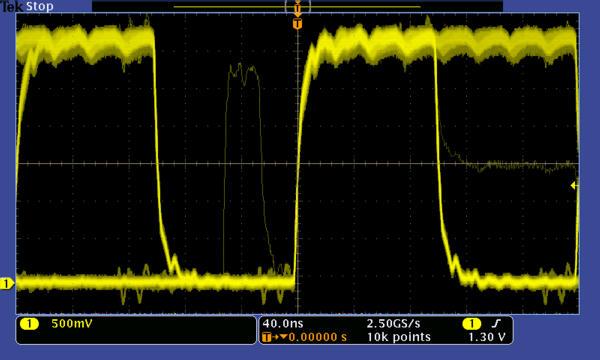
La rápida velocidad de captura de forma de onda, aumenta la probabilidad de capturar glitches evasivos así como otros eventos poco frecuentes .
Realice Depuración Serial para los Estándares Comúnes
Análisis y Disparos Seriales
Una de las aplicaciones más comunes que requiere de una gran longitud de
registro, es el análisis de datos en el diseño de sistemas embebidos. Los
Sistemas Embebidos están literalmente en todas partes. Pueden contener
varios tipos diferentes de dispositivos incluyendo, microprocesadores,
microcontroladores, DSPs, RAM, EPROMs, FPGAs, A/Ds, D/As y I/O.
Estos dispositivos se han estado comunicando tradicionalmente con cada uno
de ellos y con el mundo exterior, usando amplios buses paralelos. Actualmente
más y más sistemas embebidos están reemplazando a los buses paralelos
con buses seriales debido a que se requiere un menor espacio en el diseño,
menor cantidad de pines, menor potencia, relojes embebidos, señales
diferenciales para una mejor inmunidad al ruido y lo más importante de
menor costo. Mientras que los buses seriales cuentan con un gran número
de beneficios, también presentan desafíos mas complejos que sus
predecesores (los buses paralelos) no los presentaban. La depuración del bus
y los problemas del sistema pueden ser más difíciles debido a que es más
complicado el aislar eventos de interés y es más dificil de interpretar lo que está
desplegado en la pantalla del osciloscopio. La Serie DPO3000 resuelve estos
problemas:
Despliegue del Bus proporciona un nivel más alto, combinado con la vista
de señales individuales (reloj, datos, habilitación del chip, etc) que conforman al
bus, haciendo fácil de identificar donde empiezan y terminan los paquetes,
e identificando componentes de subpaquetes, tales como dirección, datos,
identificador, CRC, etc.
Disparos Seriales - Disparo por contenido de paquete tal y como el inicio
del paquete, una dirección específica, un dato específico, un identificador único
en las interfases seriales populares I 2C, SPI, RS-232/422/485/UART,
I 2 S/LJ/RJ/TDM, CAN, y LIN.
Decodificación del Bus - Cansado de tener que inspeccionar visualmente
la señal para contar relojes, determinar si cada bit es un 1 o un 0, combinar bits
a bytes y determinar el valor hexadecimal? Permita que el osciloscopio lo haga
por usted ! El osciloscopio puede decodificar cada paquete en el bus y mostrar
su valor en hexadecimal, binario, decimal o ASCII (dependiendo del estándar)
en la señal del bus.
Tabla de Paquetes Decodificados - Además de ver los paquetes de
datos decodificados en la misma señal del bus, usted puede ver todos los
paquetes capturados en una tabla como lo podría estar viendo en un analizador
lógico. Los paquetes se marcan con el tiempo y son mostrados consecutivamente
con columnas para cada componente (Dirección, Datos, etc).
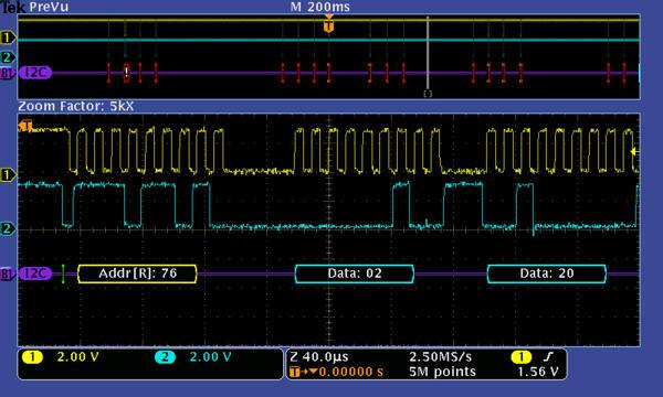
Disparo en un dato específico de un paquete de bus I C. La señal amarilla es el reloj y la señal azul es el dato. La señal del Bus
muestra el contenido del paquete decodificado incluyendo, Inicio, Dirección, Leer/Escribir, Dato y Alto.
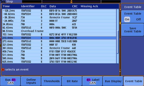
La tabla de decodificación de paquete muestra el identificador decodificado, DLC, Dato y CRC de cada paquete de CAN a lo largo de una adquisición.
Búsqueda Los disparos de buses seriales son muy útilies para aislar el evento
de interés pero, una vez que que se ha capturado y necesita analizar los datos
circundantes, que es lo que hace usted? En el pasado, los usuarios tenían
que desplazarse manualmente através de la señal, contando y convirtiendo bits,
y buscando la causa del evento. Con la Serie DPO3000, usted puede tener una
búsqueda através de los datos adquiridos por medio de un criterio definido
por el usuario, incluyendo el contenido del paquete serial. Cada ocurrencia se
se resalta con una marca de búsqueda. Una rápida navegación entre las marcas
es tan simple como presionar el botón de
Anterior (←) y Siguiente (→ ) en el panel frontal.
Diseñados para hacer su trabajo más fácil
Navegación con el Wave Inspector ®
Imagínese tratando de usar eficientemente el Internet si los motores de
búsqueda tales como Google y Yahoo no existieran, las características del
explorador tales como Favoritos y Ligas no existieran, o los proveedores de
servicio como AOL o MSN, no estuvieran presentes. Ahora ya sabe como se
sienten la mayoría de los usuarios de modernos osciloscopios cuando tratan
de usar las grandes longitudes de registro de sus osciloscopios digitales.
La longitud de registro es una de las especificaciones clave de un osciloscopio,
es el número de muestras que pueden ser digitalizadas y almacenadas en una
una sóla adquisición. Mientras mayor sea la longitud de registro, mayor será la
la ventana de tiempo que se pueda capturar con una alta resolución (alta
velocidad de muestreo). Los primeros osciloscopios digitales podían capturar y
almacenar sólo 500 puntos lo cual hacía que fuera muy difícil el adquirir toda la
información reelevante alrededor del evento que estaba siendo investigado.
Através de los años, los fabricantes de osciloscopios han conseguido ofrecer
mayores y mayores longitudes de registro para cumplir con los requerimientos
del mercado en cuanto a mayores ventanas de captura con alta resolución
hasta llegar al punto que la mayoría de los osciloscopios de rango medio ya
vienen de forma estándar o pueden ser actualizados de forma opcional a
longitudes de registro de varios millones de puntos. Estas longitudes de registro
de millones de puntos a menudo representan miles de pantallas con la actividad
de la señal. Mientras que las longitudes de registro estándar se han incrementado
considerablemente con los años y pueden satisfacer ahora la mayoría de
las vastas aplicaciones del mercado, herramientas para ver, navegar y analizar
de forma efectiva y eficiente la adquisición de grandes longitudes de registro,
habían estado muy descuidadas hasta ahora.
La serie DPO3000 está diseñada para cubrir la necesidad de trabajar con
grandes longitudes de registro con los siguientes controles innovadores del
Wave Inspector:
Zoom/Pan
Una perilla dedicada de dos niveles en el panel frontal proporciona
un control intuitivo tanto de acercamiento como de desplazamiento a través de
la grabación adquirida. La perilla interna ajusta el factor del zoom (o escala de
acercamiento); girándola en el sentido del reloj activa el zoom y va
incrementando progresivamente el factor de zoom, mientras que al girarla en
sentido contrario a las manecillas del reloj, produce una reducción en el factor
de acercamiento y eventualmente apagará el zoom. La perilla exterior produce
un desplazamiento a través de la ventana del zoom para obtener rápidamente
la porción de la forma de onda en la que está interesado en analizar. La perilla
exterior también se utiliza para determinar que tan rápido se va a desplazar
por la señal. Mientras más se gire la perilla exterior, más rápido se va a mover
la ventana del zoom. La dirección del desplazamiento se cambia simplemente
girando la perilla en el otro sentido. Ya no volverá a necesitar navegar a través
de múltiples menús para ajustar la vista del zoom.
Play/Pause
Un botón dedicado de Avance/Pausa en el panel frontal recorre
la forma de onda a través de la pantalla automáticamente mientras usted busca
las anomalías o el evento de interés. La velocidad de recorrido y la dirección se
controlan con la perilla de desplazamiento. Aquí de nuevo girando la perilla mas
lejos hace que la señal se desplace mas rápido y cambiar su dirección es tan
simple como girar la perilla en el sentido contrario.
Marcas
¿Ve algo de interés en la señal? Presione el botón Set Mark
en el panel frontal para poner una o más marcas en la señal. Navegar
entre las marcas es tan simple como presionar los botones de
Anterior (←) y Siguiente → en el panel frontal.
Búsqueda de Marcas -
No quiere gastar el tiempo inspeccionando la
adquisición entera para encontrar el evento que está buscando? Las
características poderosas de búsqueda de la Serie DPO3000 le permiten
buscar a todo lo largo de la adquisición basado en criterios definidos por el
usuario. Todas las apariciones del evento se realzan con marcas de búsqueda
y se pueden recorrer de una forma muy sencilla usando los botones del panel
frontal Anterior (←) y Siguiente (→) los tipos de búsqueda incluyen:
borde, ancho de pulso, pulso enano, lógico, setup y hold, tiempo de subida y
bajada y los contenidos de paquetes I 2 C, SPI, RS-232/422/485/UART,
I S/LJ/RJ/TDM, CAN, y LIN.
Conectividad con la PC y almacenamiento por medio
de la USB
La Serie DPO3000 le proporciona un nuevo nivel sin precedente, de operación
instantánea y conectividad con la PC por medio del USB. El puerto USB en el
panel frontal le permite una fácil transferencia de imágenes, configuraciones del
instrumento y datos de la señal, a la palma de su mano. También cuenta con un
segundo puerto USB en el panel trasero y un puerto de control USB el cual le
permite operar como puerto de dispositivo USBTMC para controlar el osciloscopio
remotamente desde una PC. Un puerto Ethernet 10/100 integrado le permite una
fácil conexión a una red. Adquirir datos y mediciones del instrumento es tan fácil
como conectar un cable USB del osciloscopio a la PC. Las aplicaciones de software
incluídas son NI LabVIEW Signal Express TE, OpenChoice y las barras para
Microsoft Excel y Word le permiten una comunicación directa y fácil con su PC.
Punta de Prueba TekVPI ®
La interfaz para punta de prueba TekVPI establece los estándares para el
uso fácil de puntas de prueba. Las puntas TekVPI presentan indicadores de
estatus y controles, así como un botón de menú en la misma punta. Este
botón despliega un menú de la punta en la pantalla del osciloscopio con
todas las configuraciones reelevantes y controles para la punta. La interfaz
TekVPI utiliza una nueva arquitectura para el manejo de la potencia
permitiendo una conexión directa de las puntas de corriente. Finalmente las
puntas TekVPI pueden ser controladas remotamente usando USB, GPIB ó
Ethernet, permitiendo soluciones mas versátiles en ambientes ATE.
Soporte para Aplicaciones Adicionales
Análisis de Potencia
La demanda por bienes de consumo está aumentando junto con la necesidad
por una mayor duración en la vida de la batería en los dispositivos y por
soluciones ecológicas que consuman menos energía, esto requiere que los
diseñadores de fuentes de alimentación tengan que caracterizar y minimizar
las pérdidas en la conmutación para mejorar la eficiencia. Además los niveles
de potencia en las fuentes, pureza en la salida y la retroalimentación armónica
hacia la línea eléctrica debe de ser caracterizada para cumplir con los estándares
nacionales y regionales de la calidad de la energía eléctrica. Históricamente,
haciendo esto y muchas otras mediciones de potencia en un osciloscopio ha
sido un proceso largo, tedioso y manual. El módulo de aplicaciones de Análisis
de Potencia DPO3PWR, simplifica enormemente estas tareas haciendo
posible un análisis de calidad de potencia de una forma rápida y precisa
pérdida de conmutación, armónicos, area de operación segura (SOA), modulación,
rizo y una rápida velocidad de respuesta -slew rate- (dI/dt, dV/dt),
completamente integradas en el osciloscopio, el DPO3PWR le proporciona
mediciones automáticas con solo presionar un botón, no se requiere de una
PC externa ni de configurar un complejo software.
Diseño y Desarollo de Video
Muchos Ingenieros de Video se han mantenido leales a los osciloscopios
analógicos, creyendo que la gradación de la intensidad de una pantalla
analógica es la única forma de ver ciertos detalles de la forma de onda.
La Serie DPO3000 con su rápida captura de formas de onda y su despliegue
de la señal con intensidad graduadada, le proporciona la misma valiosa
información de un osciloscopio analógico pero con más detalle y con todos
los beneficios de los osciloscopios digitales. Con anchos de banda de hasta
500 MHz, 4 canales y una terminación integrada a la entrada de 75 Ω , la
serie DPO3000 le proporciona un amplio rendimiento para uso de video
analógico y digital. Finalmente la funcionalidad de video de la Serie DPO3000,
se extiende considerablemente con el módulo de aplicaciones para Video
DPO3VID. Este módulo le otorga la suite de mediciones mas completa de la
industria, para disparos personalizados de video y de HDTV.
Depuración y Diseño Digital
Los diseños digitales actuales frecuentemente requieren de un cuidado en
en el trazado de los circuitos para garantizar una consistente alineación del
tiempo entre los relojes y las tarjetas electrónicas. Pequeñas diferencias en el
el retardo causadas por problemas de ruteo o por un tiempo de propagación
inconsistente a través de la tarjeta, pueden causar grandes problemas con la
operación funcional de bloques digitales. La serie DPO3000 puede ayudarlo a
encontrar esas pequeñas diferencias de corrimiento de fase que pueden
ocurrir entre los relojes conforme ellos se van migrando a través del diseño.
La pantalla XY de dos relojes puede darle rápidamente la indicación visual
de una diferencia de fases entre ellos. También pueden ser vistas rápidamente
las diferencias de frecuencia. Esto puede ser muy útil cuando se requiere
determinar que tan efectivo se está propagando el reloj o como están el resto
de las redes.
La interoperabilidad de los osciloscopios de la Serie DPO3000 con los
Analizadores Lógicos de la serie TLA5000 de Tektronix que es posible
llevarla a cabo gracias al IVIEW , permite a los diseñadores digitales resolver
desafíos de integridad de señal y depurar y verificar sus sistemas más
rápida y efectivamente. El IVIEW integra el desempeño y la exactitud en la
medición, de un osciloscopio junto con las capacidades poderosas de un
Analizador Lógico, ambos de Tektronix.
Con esta integración se le permite a los diseñadores ver la correlación de
tiempo entre los datos digitales y analógicos en la misma pantalla del
osciloscopio y aislar las características analógicas de las señales digitales
que están causando las fallas en los sistemas. No se requiere calibración
por parte del usuario. Y una vez establecida la configuración, la característica
del IVIEW es completamente automática. El resultado - un conjunto de
herramientas integradas para el diseño y la depuración digital.
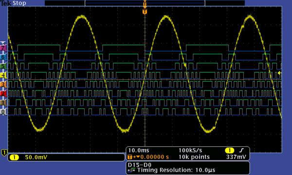
La seire MSO provee 16 canales digitales integrados que le permiten ver y analizar señales digitales y analogicas relacionadas en tiempo.
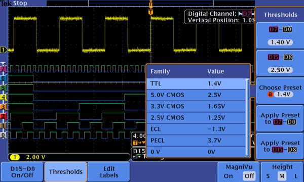
Con una pantalla en codificada en color, las formas de onda digitales tienen un color verde en los logicos 1, color azul en los logicos 0 y blanco en las transiciones. Se pueden crear grupos de canales simplemente juntando los canales y nombrando los grupos. Se pueden seleccionar niveles de umbral logico por cada POD de la punta de prueba de 8 canales cada uno. Permitiendo trabajar al mismo tiempo con hasta dos umbrales de familias logicas (TTL, CMOS, ECL... Etc.).
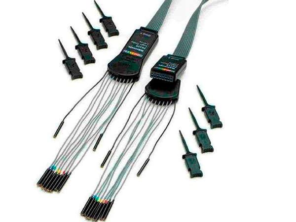
Las puntas de prueba P6316 para los canaes digitales del MSO estan incluidas y estan agrupadas en PODs de 8 canales cada una para simplificar la conexion a su dispositivo bajo prueba.
|
|
|
|
|
|
|
|
|